Wednesday, January 25, 2012

A Winder Alignment Case Study

Recently, a manufacturer of fine paper contacted American Industrial Metrology (AIM) because the paper manufacturer was experiencing issues in their two drum winder. The customer was having high vibration at full run speeds. In addition, they had a multi section dancer roll that was not maintaining its profile.

The initial survey on a winder involves establishing bench marks relative to the slides that carry the core chucks. This is critical. That is done by installing permanent brass monuments in the floor. All rolls and components are measured to this reference. From this we can produce a strip chart that maps the theoretical path of the paper through the Winder. This chart shows potential problem areas with paper tracking.
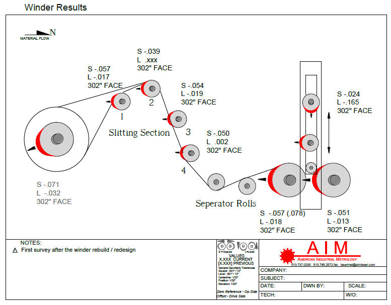


Slitting Section
• The first roll is -.057” to the entry on the drive side and -.017” low on the drive side.
• The second roll is -.039” to the entry on the drive side.
• The third roll is -.054” to the entry on the drive side and -.019” low on the drive side.
• The fourth roll is -.050” to the entry on the drive side and .002” high on the drive side

Bed Rolls
• The Rear Bed roll is -.057” to the entry on the drive side and -.018 low on the drive side.
• The Front Bed roll is -.051” to the entry on the drive side and -.013 low on the drive side.

In addition to this, AIM produced a log diameter gauge. This gauge measured the diameter of the log coming of the paper machine on both the tending side and drive side and compared them. It also measured log eccentricity. By combining this eccentricity with vibration data coming of the winder, caliper issues, loose wind issues and run speeds could be determined.

The back bed roll was corrected parallel to the front bed and to the rest of the rolls on the winder. The relationship between the Rider roll and the Bed rolls would be expected to affect product quality and cause run ability issues. The correction resulted in the bed rolls being parallel to the slitting section. The vibration issues were dramatically reduced and the alignment of the rolls allowed the winder to be operated at optimum speeds without loss of product.

Laser Alignment
The measurement and alignment in this case study was conducted with lasers. This means the data can be repeated at unrelated time intervals – over the course of the entire measurement and alignment. Because laser measurements offer “live” data, moves can be made in real-time, eliminating the need to move and recheck and then repeat until the desired alignment is achieved saving time and money.
Proper alignment of rolls to a single baseline is critical to the operation and maintenance of all the sections in a paper machine. The laser measurement techniques presented here can be applied to all sections and/or rolls – whether you are measuring and entire section or just replacing individual rolls.

Tuesday, August 9, 2011

Lunch & Learn

AIM Founder and President, Bill Wick, has forgotten more about alignment (he's old!) than most of us will ever know. Leverage Bill's knowledge in your organization by hosting a Lunch & Learn at your facility.


You provide the place, food, topic and Bill provides the answers. Example topics include:
 
1. Alignment's Role in Root Cause Analysis
2. Optimized Alignment: Industry Tolerances
3. A Planned Approach for Correcting Alignment 
4. Systems & Solutions Available through AIM

The Lunch & Learn can be formatted for management, engineering or mechanics and millwrights. The Lunch & Learn is offered at no cost, to learn more or schedule Bill contact Cheri at 513-737-0200

Tuesday, June 28, 2011

Mill Window Profile Analysis

Comprehensive Analysis
At AIM, we believe we provide the most comprehensive Mill Window Survey and Analysis in the industry. Our unique methods and tooling allow us completely and accurately map your mill window; including the vertical profile of each liner surface, mill window skew to the process centerline and the bottom liner pockets.  We also have the ability to perform a complete roll chock analysis to determine roll crossing and chock condition.


Using the window opening and skew at passline as reference, the liner positions are mapped from the bottom of the mill to the top of the mill. The results are compared to the plan to indicate possible wear or misalignment of the liners and window opening.

More Than Just Data
AIM customers receive much more than just survey dimensions and measurement data. Our reports include graphs, drawings and layouts as well as interpretations, analysis and specific recommendations. An AIM Mill Window Profile Analysis provides customers the information they need to make objective, data-based decisions to improve their rolling process.


Mill window skew is rarely considered or measured. However, the relationship of the mill window to centerline is critical, especially in multi-stand mills or reversing mills. Examples include: hot mill roughing (edge rolls) and finishing stands, tandem and reversing cold mills, as well as temper mills. Shape defects and mill control problems can develop if the mill skew is out of tolerance.

Contact AIM to learn more about the Mill Window Profile Analysis and don't forget to ask about our comprehensive Roll Chock Analysis!

Monday, June 27, 2011

Position Monitoring System - Paper Log Eccentricity

Paper Log Eccentricity Application
American Industrial Metrology offers precision non-contact position monitoring solutions. The systems measure linear position of machine components or product surfaces without the error created by mechanical clearances and backlash. The systems utilize high-precision triangulation Laser Displacement Sensors. The high-speed sensors measure the distance to a surface target. This distance is used to calculate the position of the diameter of a roll or log. The live displacement data is transmitted via a wired connection to the Display Unit processor. The data is processed to calculate machine position or other configurable position measurements.
 
AIM’s Paper Log Eccentricity System measures the outside diameter of a log of paper using two precision laser displacement sensors. By monitoring the precise position of the outer surface of the log as it unwinds on each end of the log, the relative eccentricity or diametric difference can be accurately calculated. The live displacement data is output to a digital or analog signal which can be connected to the customers control system. The display unit is housed inside an aluminum case or can be custom mounted in most operator panels. This system provides safe, real-time monitoring of the process with the ability to store and trend the data.
The position monitoring solution can be applied to a wide variety of applications. Contact AIM today to put our creativity and experience to work for you.

Friday, January 28, 2011

Go Lean And Green: Align The Machine

Did you know that approximately 50% of vibration-based damage to rotating equipment involves misalignment issues? When machinery is well-aligned, MTBF increases and power consumption drops. Not a bad way to cut operating costs!

Eighty percent of the lifetime cost of owning an electric motor is for the electricity purchased for its operation. Knowing this makes it easy to understand why even a small increase in efficiency leads to substantial savings over the life of the machine. You may have heard that precision shaft alignment makes your machines more efficient, thereby reducing power consumption. But just how does it do it? Learn more here: Go Lean And Green: Align The Machine

To learn more about AIM's precision shaft alignment capabilities contact us at 513-737-0200 or visit our website at http://www.aimlaser.com/

Thursday, January 6, 2011

Measuring Closed Or Inaccessible Rolls

Down time and through put is a big deal in any process, so any time you can measure without disassembly and incurring excessive down time it generates huge savings. American Industrial Metrology has developed and patented a process that does not require access to the roll surface to determine roll alignment.


This procedure was used in a Continuous Galvanizing line (CGL) recently to measure the rolls in the vertical furnace. The mill was experiencing as many as 15 strip breaks a month in the furnace area alone, all related to off tracking in the furnace. Using the AIM method there was no disassembly of the furnace, in fact the mill even kept heat in the furnace. A projected off tracking of as much as 3” to the drive side was predicted by the survey.
The survey took less than 10 hours to measure all of the 38 rolls. By exporting the data to AIM’s proprietary strip tracking worksheet, 2 rolls were identified as causing 80% of the tracking issues. These 2 rolls were adjusted according to the data. On startup the mill experienced almost no tracking issues in the furnace. The predicted off tracking of 0.5” was actually shown to be less in running conditions.
Subsequent fine tuning of additional rolls created a situation where the mill only experienced 2 strip breaks in the following months, unrelated to off tracking, but identified as weld related.
The mill has subsequently upgraded its drives and has been able to run at 500FPM as opposed to 350FPM and strip break incidents have been reduced further to 2 per year. This was achieved at minimal cost and resulted in a significant reduction in down time as well as a major increase in though put.

Monday, December 20, 2010

Galvanizing Line Pot Equipment Life

steel mill galvanizing line in the mid west was experiencing severe bearing wear of the pot equipment in the zinc tank. Projected bearing life was 6 weeks, but the mill was stopping production every 2 weeks to replace badly worn bearings and was running very close to complete bearing failure on several occasions.

After attempts to align the pot equipment by a local company using a Laser Tracker failed, AIM was brought in to do a survey of the galvanizing line pot equipment. A one day AIM survey, and corrections based on the survey that day, produced an immediate and dramatic change to the process. Bearing life improved to 8 weeks and strip tracking throughout the pot and tower areas improved as well.

Score: AIM = 1, Laser Tracker = 0